Understanding 3D Gaussian Splatting via Render Engines!

Michael Jernil
Tags

Introduction
So, what’s a 3D Gaussian Splat?
It’s a paint stroke in 3D space that looks different depending on where you see from. Just like every situation in your life. OK, then. Thanks for visiting!
Ahh wait… What’s a 3D Render Engine?
It’s a piece of software that enables 3D rendering on any display. OK, that’s a definition. Don’t feel like you have to stick around for the whole thing!
In case you missed it, those were jokes and we’re not just going to leave you hanging with a bit of low effort humor. The point of this post is to take a look under the hood for what is needed to display 3D objects on a screen. We’ll do this by taking a look at the First Principles of a 3D Render Engine i.e. breaking it down into its most basic components at the core. As an extension of that - we’ll look at the latest radiance field rendering technologies through the lens of these First Principles to specifically understand the recent paradigm shift in 3D scene creation, representation & rendering with 3D Gaussian Splatting!
Take a look at the 3D Gaussian Splatting scene below. This was generated using Luma AI from photos I took of a small home plant. You can play around and interact with this!
Luma Link
Just look at the details of the plant! Muaahh.. 🤌🏻✨ How real does this look and feel!!
Note that this is not a 3D mesh and it’s rather a scene represented by 3D Gaussian Splats. If you zoom in close to the model, you can see them.
Alright.. before we move on, a little bit about me - I am Michael Jernil, a Filmmaker and a 3D Graphics Engineer & Enthusiast building for 3D on the web. I was thrown into the world of Web 3D, while pursuing my interest in filmmaking, photography & game development, and then landing a job at an AR startup led by Ex-Googlers running a web platform for conversion of 3D models to web-ready formats. Since then, I have worked in a film production as an Associate Director & also have worked with multiple startups in different domains such as photogrammetry, construction and 3D visualization helping them to engineer and build 3D viewers for their web platforms.
During each instance, I had dealt with many problems which I had to solve for real-time rendering of large-scale 3D objects in a web browser without causing any lag or crashes. I had to learn to solve these things from scratch as not a lot of resources were available online during that time (surprisingly even now). I made a lot of mistakes but eventually, as you do, you learn from them & figure out how to do things better - which also led to the creation of this post!
Below are my socials. You can connect with me for a discussion, collaboration (or) if you are interested in more posts such as this! 😇
Michael Jernil - LinkedIn | GitHub | X and my One-person company - 3D ENGINERD.
With this post, we have an accompanying 3D Viewer created using Three.js, React Three Fiber, Typescript & any other libraries we need. Currently, this is a work in progress & not all features have been implemented. Below is a demo -
Demo Link
Here is the Link to the Git Repo for you to follow & keep yourself updated and the 3D Viewer is also hosted at - https://webrenderengine.vercel.app/
About 2 years back, I was tasked with building a 3D viewer for the web at a photogrammetry company (similar to RealityCapture) where the 3D viewer had to render large city-scale photogrammetry outputs with size in GBs such as Point clouds, textured 3D meshes & 2D elevation maps in real-time on a web browser with minimal loading times & smooth performance.
At this point, I had started seeing the patterns in my years of experience building 3D web apps end-to-end. So, I started creating my own methodologies to understand the scope of the problems we’re trying to solve and to organize ideas and build better. This allowed me to architect the full-stack 3D app early-on and make crucial decisions at each step such as what 3D formats to use, how to generate those formats on the cloud, taking backend decisions, cloud storage and real-time rendering on the frontend etc.
One of the important methodologies I decided to try for building this huge-scale 3D Viewer was the First Principles approach, after I heard about it in one of Elon Musk’s interviews about SpaceX.
When I chose to go this way, the First Principles helped me to break down and approach the building of the 3D viewer app in a fresh way, helping to plan the development in its initial stages, saving a lot of confusion in the later stages. We’ll be looking at this approach in a few minutes, but before that, let’s start with the most important question here:
What exactly is a 3D Render Engine?
A 3D Render Engine is any piece of code or software that we can use to render 3D objects on a screen.
Much like a car engine - that takes in fuel, combusts it in the cylinders that produces mechanical energy, and then rotates the car’s wheels, a 3D Render Engine - takes in 3D models & the description of a 3D scene and processes the same to calculate the colors, lighting, and shading for each pixel in a screen, producing a final 2D image or a series of images, which can be a still frame or part of an animation.
Render Engines are at the core of a wide variety of 3D applications from video games, 3D modeling / VFX software, game engines and various visualization tools used for ArchViz, GIS & Data Visualization.
Some examples of Render Engines are - Any 3D Viewer Software, Real-time Engines such as - Blender Eevee, Unreal Renderer, Unity or any Game Render Engine etc. & Offline Render Engines used primarily for CG in movies & animation such as Blender Cycles, Octane Render, Pixar’s Renderman etc.
What is Real-Time and Offline Rendering?
“Rendering can be split into two main categories: Real-time rendering (also known as online rendering), and pre-rendering (also called Offline rendering). Real-time rendering is used to interactively render a scene, like in 3D computer games, and generally each frame must be rendered in a few milliseconds. Offline rendering is used to create realistic images and movies, where each frame can take hours or days to complete, or for debugging of complex graphics code by programmers. ” - Wikipedia
What are First Principles?
Breaking down a problem into its First Principles means essentially breaking down a problem into the most principle atomic components, so that we can see what it’s made of. Then we could use that understanding to figure out ways of solving the problem better.
In the words of Elon Musk - “Boil things down to the most fundamental truths and say, ‘OK, what are we sure is true, or as sure as possible is true? And then reason up from there.”
The following excerpt from the blog post on first-principles explains a bit further -
First principles thinking, which is sometimes called reasoning from first principles, is one of the most effective strategies you can employ for breaking down complicated problems and generating original solutions. It also might be the single best approach to learn how to think for yourself.
I specifically like the last line, which says that it’s an approach that can help you to think for yourself. This could be the case for any problem that you take in any domain, but it specifically applies to engineering and development really well.
Below is the talk from Elon Musk discussing First Principles. Feel free to check it out.
Okay, here are the First Principles of a Render Engine for 3D Gaussian Splatting. We’ll be getting to this by the end of the post, where you will gain a clear understanding of what 3D Gaussian Splats are!
Render Engine - First Principles
Now that you’ve had a glimpse of what First Principles are, let us look into what makes a Render Engine, by breaking it down into its First Principles. This will help us understand what goes into building a 3D Render Engine, and it could help us build our own from scratch, or modify parts of an already existing engine.
We’ll look at this specifically from the lens of web-based render engines i.e., software that renders 3D scenes in a web browser, although the components are almost the same for render engines that run on native devices. More than building a render engine from scratch, this post is to help you understand the core components of a render engine so you could build your own render engine for any application end-to-end!
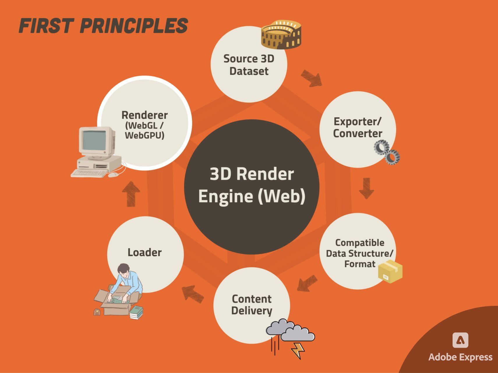
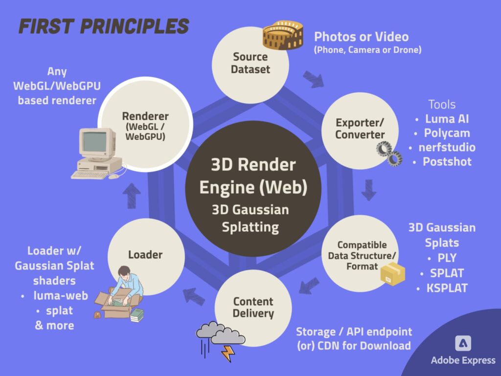
In the above diagram, you can see that we were able to break down a 3D Render Engine into its 6 First Principles. Let’s look into what each of these are!
Source Dataset
The dataset you want to visualize in real-time, in its original format.
Imagine you want to render Vice City in the upcoming video game - GTA VI, then the source datasets would be the 3D models (assets) of the player character, NPCs, vehicles, roads, buildings, garbage bins etc. & their corresponding textures, and scene information containing the placements of these assets, lighting information etc.
In short - these could be the assets created by 3D artists, Environment artists or photo-scanned models.
Some examples:
Textured 3D Mesh - OBJ, FBX, glTF, USDZ
Point Cloud - LAS, LAZ, PLY
CAD Models - STEP
Building Models - IFC, RVT
Elevation Maps - TIFF, GeoTIFF, PNG
Compatible data structure (DS) / format
The right data structure / file format that would facilitate seamless rendering of your Source dataset in real-time.
When it comes to picking a file format or data structure for a 3D dataset to render in a web-based render engine, a few considerations are necessary by default. Of those potential considerations, the two primary ones are:
Loading times: When it comes to loading times, if the dataset that needs to be loaded exists on the user’s device, then it can be loaded very fast from the disk storage. But mostly the dataset may not be available on the user’s device & in this case, the loading time it would take for the device to download the dataset over the internet and then display it, must be considered. Say, in our web render engine, if we want to render a 3D Point cloud of a city that is approximately 6 GBs in size - then do we make the user wait, the total time it takes to download the whole Point cloud model so that it could then be viewed in real-time? This wait could be a couple of minutes or much more than that, depending on their network speed. If it’s a relatively smaller dataset, say 100 MB in size, the wait time could be just a couple of seconds and it wouldn’t be much of a hassle.
Performance: Rendering performance can be judged on FPS - frames (rendered) per second. More FPS means much smoother performance. Think of all the video games that are branded as 4K 120FPS. They seem to be putting forward the message that they can provide an immersive playing experience. In terms of a render engine, this could mean a number of things. But one core component that dictates performance is hardware. This gets tricky when thinking of building a 3D web application, because this may need to run across a multitude of user devices, ranging from a $200 phone to a beefed-up gaming PC with an RTX 4090 Graphics card.
For the sake of the considerations discussed above, efficient data structures, file formats and rendering techniques have been developed over time so that these problems could be addressed! Those are - Spatial acceleration/hierarchy structures, View dependent rendering & Levels-Of-Detail (LODs). For now - just register these fancy terms in mind. We’ll circle back to them later in this post in an effort to understand each!
Some examples of widely-used 3D File Formats and Data Structures for Real-time Visualization are - File Formats: PLY, LAS, glTF, USDZ, SPLAT. Data Structures: Potree (Octree-based DS for huge Point clouds), 3D tiles (Grid-based DS for large 3D Meshes)
Exporter / Converter
Any tool or library that can be used to convert source 3D dataset to your required data structure / format.
For converting the Source dataset into the required Compatible data structure / file format, an exporter in any 3D application like Blender, Maya etc. or other Converter libraries / tools could be used.
Storage
An accessible place to store your converted dataset in the corresponding Data Structure or Format.
Now that we have the 3D dataset, or the fuel, if we were to stick to our car analogy, we need a safe place to store and access this fuel, as and when needed. For a web-based 3D viewer, this means storing the dataset in a place from where it could be accessed through network requests to an API endpoint or CDN. So, naturally Cloud Storage solutions like AWS S3, GCP Cloud Storage or self-hosted would be good choices.
For native applications, this could be the hard disk of the local system that is running the 3D software. The data could be compressed or encrypted at this stage, if required. Some types of compression can also reduce the file size by a significant amount, provided it has a corresponding fast decompression method that could be used in the frontend when loading the data.
(Please note that the Storage First Principle is not mentioned in the above diagram. For simplification purposes - it is combined with Content Delivery)
Content Delivery
How the content (in its current form) can be delivered to the client from storage.
So, now we have fuel stored away in a safe place that is accessible. But how do we reach it when it’s required? We rely on a Content Delivery Network (CDN) or Cloud storage endpoints. Through the use of an API / network request, we retrieve the data required with the response data of the request (also this is how any internet download works). Additionally, most cloud storage providers like AWS S3 also support byte range requests.
Byte range requests are network requests that don’t ask the web server to serve an entire file. Instead, it requests the server to only download a specified portion of the file. This comes in handy for on-demand streaming and rendering (for large-scale point clouds, 3D tiles or geo raster rendering) for the concerns we discussed above regarding loading time & performance.
Imagine when you’re streaming a movie on Netflix - you don’t have to download the entire movie, before you can start to watch it! There, each movie frame is being streamed to your device at high network speeds and 24 or more frames per second are being rendered real-time.
Loader
The Loader prepares the Data Structure / Format so that it can be readily used for the renderer to render the 3D data.
Now that the fuel has been accessed, we need to load it into the Engine to use it. This preparation may include storage endpoint access, file read, decompression/decryption, loading data into geometry objects for draw calls etc.
Libraries like Three.js offer their own loader libraries for common data formats like OBJ, glTF, PLY, USDZ etc. that works seamlessly with its renderer.
Renderer
This crucial component will render your 3D data as pixels on a screen. For any 3D engine, making the right choice of a renderer is essential.
This is the core part of the engine that takes in all the necessary data and renders them as pixels on a screen. Sometimes it can render them at 24 to 60 FPS or more, giving us the real-time 3D renderer. If you’re wondering, 24 FPS is the cinema or motion picture format that we’ve all grown to love, and 60 FPS or more is the smooth gameplay experience that modern video games entice us with!
For building a web-based 3D viewer, we could use either Three.js or BabylonJS - These 3D libraries are built as an easy-to-use abstraction on top of web graphics APIs such as WebGL, WebGPU. For desktop applications, there are low-level graphics APIs such as Metal, Vulkan, DirectX etc. You could choose to build your own renderer from scratch using any of the graphics APIs mentioned above. But we will not be exploring that in this series. Rather we will use Three.js as the core library on which we build our Render Engine.
From here on out, let’s look at what it takes to build a working 3D Render Engine - by using First Principles thinking to render different kinds of 3D data in real-time.
Basic 3D Model Viewer
We’ll start by building a simple 3D Model viewer for rendering Textured 3D meshes that is in a commonly used 3D file format like OBJ and examine what decisions & choices we need to make to build this viewer.
We will follow a step-by-step process of using the first principles we saw earlier to take decisions such as architectural concerns, spatial data structures, 3D rendering, cloud storage, and more.
Let’sss go! 🔥✨

Source dataset
Almost all 3D software export 3D assets in OBJ format. We’ll consider our 3D asset to be in this format.
Compatible Data Structure / Format
We need to decide what file format would be best to render this 3D asset in our web-based viewer. glTF (Graphics Library Transmission Format)& USD (Universal Scene Description) are two widely adopted web-ready formats - meaning they’re meant for the web and structured in a way that can be easily stored and accessed or streamed over a web network. We’ll pick one of these. glTF is an open format developed for ease of transmission and interoperability of 3D formats across the web & its compressed format is known as glb. USD is the standard interoperability format introduced by Pixar & used for 3D applications of Apple systems (MacOS, iOS). USDZ is the zipped version of USD.
Exporter / Converter
Now that we’ve decided the desired 3D format for final rendering, let’s find a way to convert the Source 3D asset to our desired format. 3D modeling software and Photogrammetry applications like Blender, Maya & RealityCapture may provide the glTF & USDZ formats in their in-built exporter. We could use any of these to generate the compatible model files in glb/glTF or USDZ formats. We can use libraries such as obj2gltf & obj2usdz for the conversion of OBJ models to USDZ or glTF formats.
Storage
We can pick a cloud storage solution that fits within our needs. Ex - AWS S3, Google Cloud Storage etc., or we can give the user an option to pick files from their disk storage.
Content Delivery
Cloud storage solutions usually provide signed or public URLs that could be used to access a specific file. They also provide APIs to pre-sign URLs from your web server. We could also choose to use a CDN or host our 3D model at a public URL and access it from there.
Renderer
Before looking at the loader, let’s look at our renderer so we can pick a loader that’s compatible with this. We will pick Three.js as our renderer. There are also libraries that could be used for writing the renderer using Three.js in declarative React such as react-three-fiber.
Loader
Since we’ve picked glTF & USDZ to be our usable data formats, we’ll need loaders that could be used in tandem with our Three.js renderer. Fortunately for us, the official Three.js repository provides a glTF Loader and a USDZ loader which we can use to load our datasets.
We now have the knowledge needed to build a very simple 3D viewer, which can be used for viewing a single 3D object. You can take a look at the viewer built here using React Three Fiber. We’ll be continously updating the code at this repo. So you can Star ⭐️ it to keep yourself updated!
So, now off to render a photoscanned city - that’s either a Point cloud or a 3D Textured Mesh. Wow, that’s a big jump from rendering a small 3D asset. It’s okay, let’s go for the highest possible goal that we can achieve✨ Let’s take this First principles approach to see how we could build a 3D Viewer for much bigger homogeneous 3D assets 🌎. Homogeneous means it contains only one type of 3D data.
Large-Scale Point Cloud and 3D Mesh Viewer

Source dataset
When you scan huge cities and landscapes and process it through a Photogrammetry software (like Reality Capture), the outputs are naturally larger in size. The resulting scanned 3D model could be a Point cloud and/or a 3D textured mesh generated from the Point cloud.
Point clouds consists of raw colored points in 3D space and can hold points in number of millions or billions. You could see how it could easily be a massive amount of data. Textured meshes are generally smaller compared to point cloud, since they have connected polygons and textures (structured data) instead of unconnected points and colors (unstructured data). For instance, a wall of a building could be represented as a 3D mesh using a polygon with 4 vertices and a corresponding wall texture - whereas to represent the same wall as a point cloud, it could need hundreds or thousands of points each with their own color, depending on the visual quality of the wall.
Okay, now let’s finalize the source datasets that we’re looking to render in real-time:
Point cloud
Format: LAS
Scale: millions to billions of Points
File size: let’s say 20-50 GBs.
3D Textured Mesh
Format: OBJ
Scale: huge scale with high poly counts
File size: 5-10 GBs
Now that we have our dataset defined, let’s go through the other items necessary to build this viewer.
Compatible Data Structure / Format
When we’re trying to render large-scale 3D models, the concerns we had already discussed in terms of loading time & performance are amplified. Imagine we load the source dataset as is, on a web browser. The user might have to wait eons to download a 10GB point cloud, only to have their GPU struggle to render it, and this will most likely end up crashing the browser. 💀
This is where the fancy terms from earlier - Spatial Hierarchy Structures, Levels-Of-Detail (LODs) & View Dependent Rendering come in!
Let’s look into how these can help in loading and rendering huge 3D models.
(You can skip these sections if you’re that fancy person familiar with these concepts already!)
What are Spatial Hierarchy Structures?
Well.. It could be a term from the Victorian era explaining how the British kingdom was structured for maximum colonialism of the world.
Or it could be a less interesting one. Unfortunately for us, it’s the latter.
When you’re playing a video game or watching an animated movie with really detailed graphics - the computer has to load and display all the 3D objects and scenes, but it can’t do all of this at once because that would be too slow and it would also take up too much memory. So, it uses something called Spatial hierarchy structures to organize things more efficiently.
Spatial hierarchy structures are a way of organizing the objects in a 3D scene based on their positions in 3D space. It’s kind of like putting things into folders on your computer to keep them organized, but in this case, it’s about where things are spatially located in a virtual 3D world.
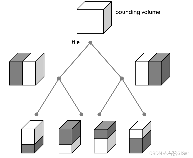
One common type of Spatial hierarchy structure is a “Bounding Volume Hierarchy” (BVH). Picture a big box that contains everything in a certain area. Inside that big box, there might be smaller boxes that each contain a specific part of the scene. This continues until you have really small boxes that only contain a few things. It’s like a tree structure where each level gets more and more detailed.
Now, here’s why it’s useful:
Efficient rendering: When you want to draw or render a scene, you don’t have to look at every single object. The computer can quickly figure out which big boxes don’t need to be drawn because they’re too far away or hidden behind other things. This saves a lot of time and makes things run faster.
Collision detection: If your game character needs to know if it’s bumping into something, the spatial hierarchy can help. Instead of checking collisions with every single object in the game, it can quickly figure out which parts of the scene are close enough to check for collisions.
Optimizing performance & saving memory: Since you’re not wasting time on things that aren’t visible or relevant, your computer’s graphics card, RAM memory and processor can focus on what’s important. This helps make sure the game or animation runs smoothly without slowing down and without overloading the computer and graphics memory.
So, in a nutshell, spatial hierarchy structures are a smart way of organizing and managing 3D scenes to make them look great and run smoothly in applications like video games and other render engines.
“LODs? …Lord Of the Ducks?”
Nah… LOD stands for “Level of Detail”. It’s a technique used in 3D rendering to manage the complexity of objects in a scene. Imagine you’re playing a video game or exploring a 3D environment, the LOD system adjusts the level of detail for each object based on how close or far away it is from your viewpoint.
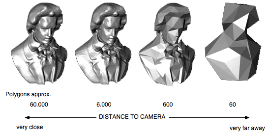
Here’s a breakdown:
High detail (close up): When an object is up close, like the character you’re controlling in a game, the LOD system uses high-detail models. These models have lots of polygons and textures, making them look super detailed and realistic.
Medium detail (mid-range): As you move away from an object, the LOD system might switch to a medium-detail model. This model has fewer polygons and less detailed textures. It still looks good from a bit of a distance, but it’s not as intricate as the high-detail version.
Low detail (far away): For objects that are really far away, the LOD system switches to a low-detail model. This one has even fewer polygons and simpler textures. You might not notice the lack of detail because the object is so distant, and using a less detailed model saves a lot of processing power.
So, why do we use LODs?
Performance optimization: Rendering highly detailed 3D models is computationally expensive. By using LODs, the system can focus resources on what’s currently important, making the rendering run more smoothly.
Maintaining frame rates: In video games and other rendering applications, maintaining a consistent frame rate is crucial for a good user experience. LODs help ensure that the frame rate stays high even in complex scenes with many objects.
In summary, LODs are a smart way of showing you the right level of detail for each object, depending on how close or far away it is. It’s about balancing visual quality with performance to give you the best overall experience in a 3D environment.
“View Dependent Rendering, amirite?”
What if the world, and the buildings & objects in it, started appearing as and when you walked and moved through space, and the parts of the world outside your view just disappear? Think about it for a minute!
*INCEPTION MUSIC FADES IN…*
Wait, is this post real??! Sorry.. got a bit too excited.
Alright, let’s break down what View-dependent rendering is. Say you’re playing a video game, and your character is exploring a big virtual world. View-dependent rendering is a trick that helps make things look really great without overloading your computer.
What you see is what you get!
Instead of spending a ton of computing power to make everything in the game look incredibly detailed all the time, View-dependent rendering focuses on what you’re looking at and from where. If you’re facing a mountain, it makes the mountain look amazing. But if you turn around and the mountain is behind you, it doesn’t waste resources rendering it. And it the mountain is far, it doesn’t bother making it super detailed because you can’t notice it from afar.
It does so by making choices on which Levels-Of-Detail(LODs) to render & when. It could also use Spatial hierarchy structures to understand which parts of the scene are in view, and how close or far away they are, from the camera.
Now, how does it work tho?
For that, we need to first understand what a Camera frustum is:
A Camera frustum in 3D represents the region in 3D space that a camera can capture, defined by its near and far clipping planes, field of view, and aspect ratio. Objects within this frustum are visible in the camera’s view.

In View dependent rendering, A Camera Frustum Hit test happens with each frame being rendered, checking what objects or items of the Spatial hierarchy structure collide with the camera frustum i.e. what objects/areas are in view of the user and depending on that, only the hit areas are rendered. This also helps to identify what portions of the 3D scene are near to the camera and what portions are far away, and this could be used to render closer objects with higher LODs and farther ones with lower LODs.

Imagine this to be a top down view of the 3D world that we’re trying to render and it is spatially structured as grids (or) BVHs. The 2 thick red lines - being your line of sight(camera frustum), grey - being the area that should be rendered. The size of the grids represent the higher or lower LODs. And the smaller red grids - is the area that are out of view and don’t need to be rendered.
For better loading times and smooth real-time performance - View dependent rendering, Spatial hierarchy structures and LODs are used together to get the best results. It’s all about displaying your virtual 3D world both beautiful and fast, no matter its size!
Alright, let’s now pick the Spatial hierarchy structures / Data Structures that we would need for rendering our huge-scale Point cloud & 3D Textured mesh.
For the Point cloud, let’s choose an Octree-based Spatial hierachy structure with point density based LODs called the Potree format.
For the 3D Textured Mesh, we’ll pick a Grid-based Spatial hierachy structure with mesh decimation based LODs called the 3D tiles format.
Exporter / Converter
There are good open source Converter tools or libraries that we could use to convert our Source datasets to the now required Data structures such as:
There might be use cases depending on your application where the user uploads the Source dataset directly on your web application. In that case, we may need to take care of this conversion ourselves in the backend by running these conversions on our servers or cloud using certain services such as server instances, microservices, batch process etc. and then save the output file in the corresponding Storage.
Storage & Content Delivery
We can pick a cloud storage solution that suits our needs. In this case, we’ll need a cloud storage solution that definitely provides support for streaming data, as we’ll be making queries to fetch selected data depending on the camera view. We’ll be using the byte range requests that we had talked about earlier for this. We can choose AWS S3, as it provides good streaming support & API for pre-signed URLs.
Alternatively - we could give the user an option to store and use any dataset from their local storage, given it is in our chosen compatible format (Potree / 3D Tiles).
Loader
So, the Loader libraries for our chosen ones - the 3D Tiles & Potree formats exist in the open source world of Github. We can pick some reliable loaders from there. For 3D Tiles, we could use three-loader-3dtiles by nytimes. For Potree, we could use three-loader by pnext.
Renderer
Again our go-to choice for Renderer is Three.js, and it’s WebGL Renderer. We can build it using react-three-fiber(R3F).
Now that we have done the thinking and made the choices necessary to build this 3D Viewer / Render Engine that can render Point clouds or 3D mesh of a huge landscape or city, we have the necessary knowledge to draw out an architecture comprising of the backend, frontend etc. and start building the Application. The Architecture would differ depending on your use case and how your web app is going to be structured!
The development for this viewer is still in progress at the Viewer repo, and will be updated once done.
Now that we have developed an essential understanding of how 3D rendering on the web works for various types of 3D data and the corresponding first principles, let’s look at how the new form of 3D scene representation - 3D Gaussian Splatting & Radiance Fields✨ fits within this narrative and try to understand how it has shifted the paradigm of 3D Scene Representation & Rendering.
3D Gaussian Splatting ✨🎨
Through the Lens of Render Engine - First Principles 🤌🏻
Gaussian Splatting Representation
Earlier, when we spoke about rendering different types of 3D objects or scenes, it involved converting a Source 3D dataset into a 3D representation that can be easily loaded & rendered by the web-based viewer in Real-time.
With the latest advancements in computer graphics, a new Pandora’s box has been opened called - ‘3D Gaussian Splatting‘. It works on the concept that real world scenes could be efficiently represented as 3D Gaussian Splats (3DGS) - as an alternative to traditional mesh representation which involves - polygons, meshes, textures, lighting etc.
Earlier, our datasets were 3D models or assets - which are primarily meshes made up of connected triangles or quads (polygons) and contain textures - created by a 3D artist and Point clouds generated by classical photogrammetry techniques.
In the case of 3DGS, the base dataset are photos or video taken of an object or a scene in the real world, which has then been processed to generate a realistic 3D scene representation using 3D Gaussian Splats.
This 3DGS representation has the primary advantage that huge real-world scenes which are otherwise generated by classic photogrammetry techniques & complex to render using traditional computer graphics techniques, could now be represented as 3D Gaussian Splats, which you can imagine as paint strokes(splats) in 3D space with a shape, color and transparency value around the center, which also changes depending on from where (or) how the scene is being viewed (aka the camera viewpoint). When multiple of these strokes are rendered with proper blending of transparency from each splat, it can form a near realistic 3D image that can be viewed from any angle.
The advantage with this method is also that it can reproduce accurate reflections on a surface since this method tries to reproduce the real image from the source dataset & can store and display anisotropic (directional) effects.
3DGS representation is much similar to Point cloud, both being unstructured 3D data, but differs in that instead of colored points, 3DGS uses view-dependent transparent colored gaussians, which are rendered as Splats blending together to form the final image.
Before moving on, let’s look into a few basic rendering terms, that you will need to know before you can delve deeper into understanding 3D Gaussian Splatting.
What are Primitives?
No.. they’re not the people who discovered fire!
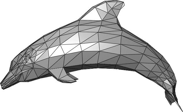
Rather, Primitives are three-dimensional geometric shapes that are the building blocks for creating complex geometric objects. A triangle is a primitive formed by 3 vertices. It is the 2D shape with the smallest number of vertices, so renderers are typically designed to render them. Triangle is a great primitive mostly used to represent & render 3D meshes. Similarly, the primitive used by a Point Cloud is a point.
Structured & Unstructured Data
For the sake of our post, you just need to know that Point clouds are known to be unstructured data because they contain points in 3D space with a color value that don’t have any connection information between them, whereas 3D meshes are structured data, since here each vertex has a connection with another vertex to form an edge which then connects with other edges to form a face(triangle/polygon), which can then be used represent a mesh with multiple other faces. This also means it’s easier to render Point Clouds than 3D mesh, as not a lot of computation needs to be done to read and render points as is.
What is Rasterization?
Rasterization is the most commonly used (rendering) technique of generating the final image that will be displayed on the screen by projecting the 3D primitive data on the screen as 2D primitives and filling the pixels with color accordingly. It also discards pixels outside the 2D primitive and checks the triangle depth in 3D space to determine which triangle should be displayed on front when there is an overlap. (Imagine the case where there is multiple triangles/meshes in the 3D scene)
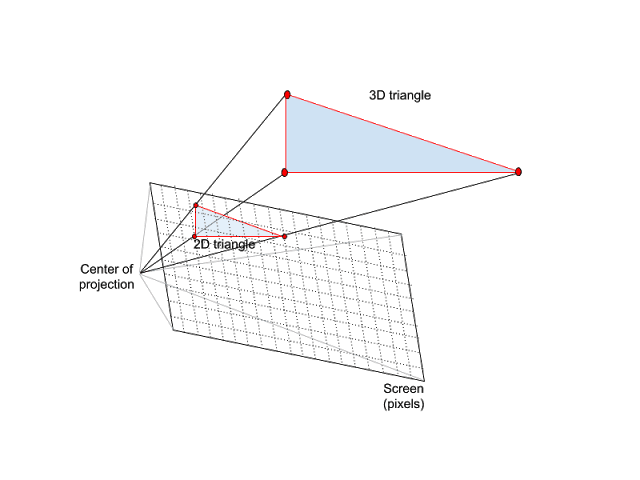
The Center of Projection would be the User’s/Camera viewpoint.

3D triangle displayed as pixels on a screen.
What are Splats?
Splats or Splatting is a computer graphics technique that was first introduced in 2001. It has since been used in computer graphics in different ways. For examples, in case of rendering Point clouds, splats have been very useful in improving the visual quality of Point cloud representations. When shading each point primitive in front of the screen with a color, it takes into account the color of the points behind the point, and renders Splats that blend points really well visually, helping to render Point clouds with better visual quality.

Point cloud render without splatting.
Point cloud render with splatting.
You can see in the above images how splatting provides better visual quality in rendering of Point clouds. Source: Potree.
Alright, now what are GSplats? G-Splats… Gangsta Splats..? maybe.
GSplats is a slang term that has been catching up recently to use for 3D Gaussian Splatting.
3DGS, GS, GSplats, GThang… call it whatever you want, but let’s now look into what a Gaussian Splat is.
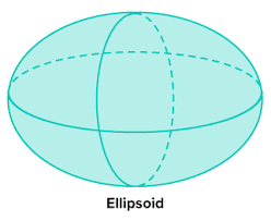
First, let’s see what primitives are used in 3D gaussian splatting. 3D gaussian splatting uses 3D gaussians as a flexible and efficient primitive to represent a 3D scene. A 3D gaussian is an ellipsoid, which is a 3-Dimensional version of an ellipse. The paint strokes I had mentioned about earlier are in fact these Gaussian ellipsoids. Think of a GSplat scene as more like a 3D photograph, where each pixel is replaced by a 3D Gaussian.
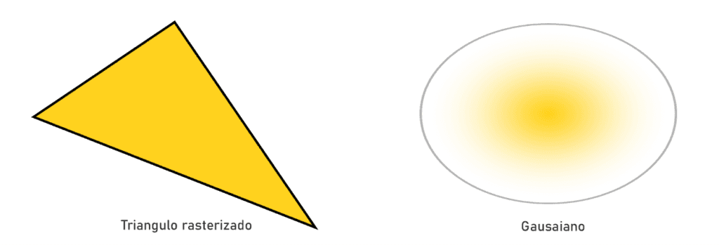
Left: A triangle primitive normally used for visualizing 3D objects using rasterization. Right: A 2D gaussian used in case of Gaussian Splat rendering. Source: taken from here.
Like how Point clouds represent a 3D Scene as colored points in 3D space, 3D Gaussian splats represent 3D scenes using 3D gaussians that don’t just have a color value alone, but holds additional information which helps to render the Splats with much closer photorealism than Point clouds which are generated by classic image-matching methods of photogrammetry.
Source: Taken from here.
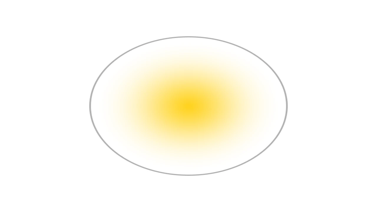
This is how a Gaussian Splat looks like - with its color, transparency & shape. Source: taken from here.
In Gaussian Splatting, each one of these gaussian ellipsoids in 3D space has these parameters:
Position: where it is located (XYZ)
Covariance: how the ellipsoid stretches/scales i.e. its shape & size (as a 3×3 matrix)
Color: Red, Green, Blue - Color Value
Alpha: its transparency (α)
3D Gaussian splatting gives a reasonably compact representation of the 3D scene, in part because highly anisotropic volumetric splats can be used to represent fine structures compactly. Say, 1-5 million gaussians could be used to represent a scene with detailed structures, whereas for point clouds, more than 10s of millions (or) billions of points may be necessary for the same. This means that GSplats considerably reduces the size of data needed to represent a scene without sacrificing on quality.
The quality of the parameters of the covariances of the 3D Gaussians is critical for the compactness of the representation since large homogeneous areas can be captured with a small number of large anisotropic Gaussians.
What is Anistropic?
Anistropy is the property where an object can have a different value (when viewed) from different directions and this property of our gaussians is also how Gaussian splatting is able to represent realistic reflections, because think about it - when you look at reflections in a puddle of water , the reflections move as you move around. To represent these Anistropic effects, GSplats use something known as Spherical Harmonics (SH). Each gaussian has a SH coefficient that helps it to store and render its directional properties (covariance, color).
To summarize - GSplats leverage the power of anisotropic 3D gaussians as a flexible representation of 3D scenes with great visual quality.
Gaussian Splatting File Formats
Since the GSplat representation is much similar to Point clouds, It uses the commonly used PLY format (.ply). There’s also similar newer formats that are being developed in the open source world for GSplats such as .splat and a compressed .ksplat format. Keep an eye out for more formats popping up as this is a rapidly developing area!
So now - according to our Render Engine - First Principles, the Source dataset for 3D Gaussian Splatting is Photos or Video taken of a real world object or scene and the Compatible Data structure/ format is a PLY, SPLAT or KSPLAT file containing 3D Gaussians data.
Considering Storage & Content Delivery, since this is a compact representation in the size of a few 10 or 100MBs, streaming support may not be needed. Although some GSplat loaders such as luma-web do use progressive loading & rendering, starting from the center of the scene and loading more splats as they are being downloaded, which can significantly reduce the initial loading time. So Storage can be done in any Cloud storage like AWS S3, GCP Storage and the Content delivery could be done via API Endpoints or CDN, with byte streaming if necessary.
Before moving on to how GSplats can be created - let’s briefly look into what novel view synthesis is.

Novel view synthesis, my good sire? Novel-view synthesis is the task of generating new images that render the object from a different viewpoint than the one given. It is a form of reconstructing a Real world scene with images as input. 3D Gaussian Splatting is one of the recently-introduced efficient and fast ways of doing novel view synthesis, and at its core is the 3D Gaussian representation.
Now, let’s look into what Exporter (or) Converter could be used now to convert our Source dataset (photos or video) into the 3D Gaussian Splatting formats.
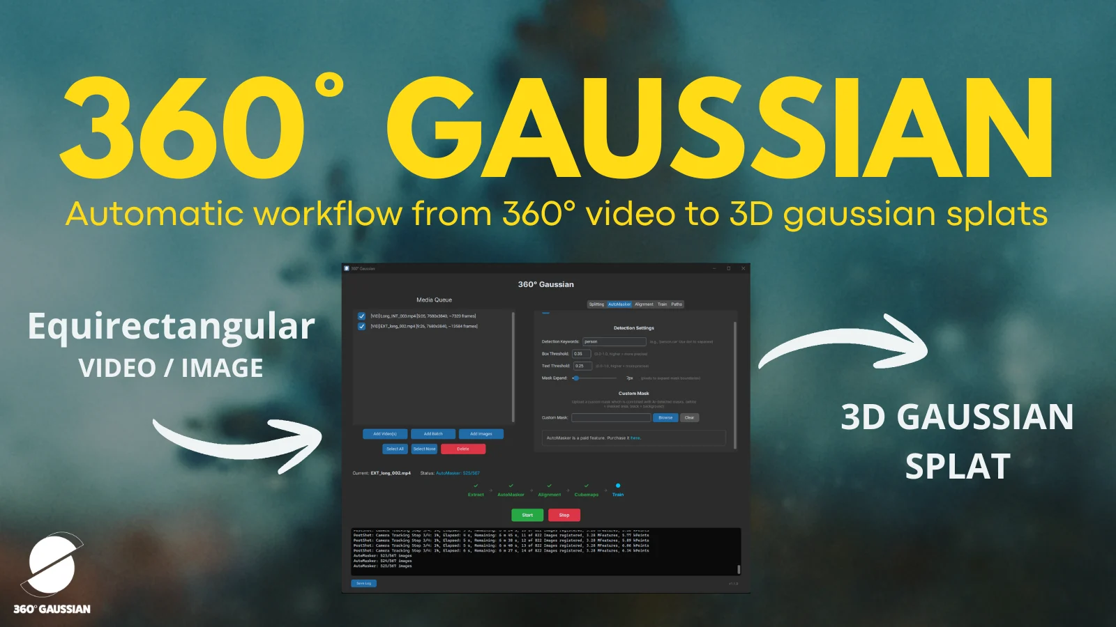
Creating your own Gaussian Splatting Captures
Awesome tools such as Luma AI & Polycam have been developed, since the introduction of 3D Gaussian Splatting for creating GSplat files from photos or videos taken on a phone, professional camera or drone. Once the source video/photos have been uploaded, these tools run the necessary processing on the cloud & generate the GSplat files, primarily in .ply or .splat format, which can then be visualized within the respective tools.
Luma Example
Bringing back this example of a home plant that you saw earlier. I got to create this scene by taking photos with the Luma app on an iPhone. They have a guided camera tool that can help you with getting good quality photos for optimal reconstruction results. You can also upload your photos or video directly on their Web platform or the iOS app.
Behind The Scenes: What it takes to create Gaussian Splatting Magic ✨
In order to understand how a GSplat scene is created, let’s take a look at the steps in the process.
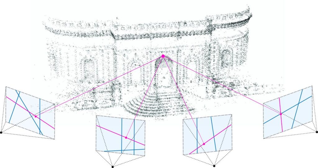
Structure From Motion: Structure from Motion (SfM) is the process of estimating the 3D structure of a scene from a set of 2D images. In this step, our source images (or frames extracted from video) are placed and aligned in a 3D space according to their perspective of the scene, same real world points from these perspectives are matched in the different images and then a colored point cloud is generated, which is a sparse 3D Point cloud representation of the scene. Libraries like COLMAP could be used to do this.
Converting each Point to Gaussian: Now, the preparation happens. Each point of the Point cloud is converted to a Gaussian, with just position and color value as only those can be inferred from the SfM data.
Training: Now we train each gaussian to best represent the source images - which is the process of figuring out and fine-tuning the gaussian parameters - covariance(shape) & alpha(transparency) in addition to the color and position we have as a result of the previous step. This is where machine learning comes in.
Technically, this step is known as optimization, we basically optimize for each gaussian to best represent the corresponding image dataset and put in the resulting gaussian parameters into each gaussian.
For this optimization, a Stochastic Gradient Descent, which is similar to a neural network is used.
Stochastic gradient descent is an optimization algorithm often used in machine learning applications to find the model parameters that correspond to the best fit between predicted and actual outputs.
In this step, the gaussians that were created in the 2nd step, with colors and positions are projected from a perspective & rasterized into a low quality Rasterized 2D image (this will now be in 2D space like the source 2D images) and this will be the predicted output.
The rasterization technique used here is a fast differentiable Gaussian rasterization method, which is the same method we’ll be using to finally render these 3D gaussians onto a 2D screen. We’ll be looking at this in a while.
Okay, now the Source 2D image with the similar perspective as the projected image of the scene will be the actual output.
The training or optimization calculates the loss based on the disparity between the rasterized image and the source image, and then adjusts the gaussian parameters (position, color, shape/size, transparency) based on the loss, and this training can continue through a lot of iterations as needed - optimizing to get that loss as low as possible to get a great quality representation of the scene, using 3D gaussians.
Also adaptive density control of the gaussians is done, which is the splitting or creation of new gaussians from each of the gaussians, as required to best represent specific details in a scene.
This is a simple visualization using a single image to show how Gaussian splats optimization occurs from the early rasterized image (projected 2D gaussians) to get to the final(source) image. Source.
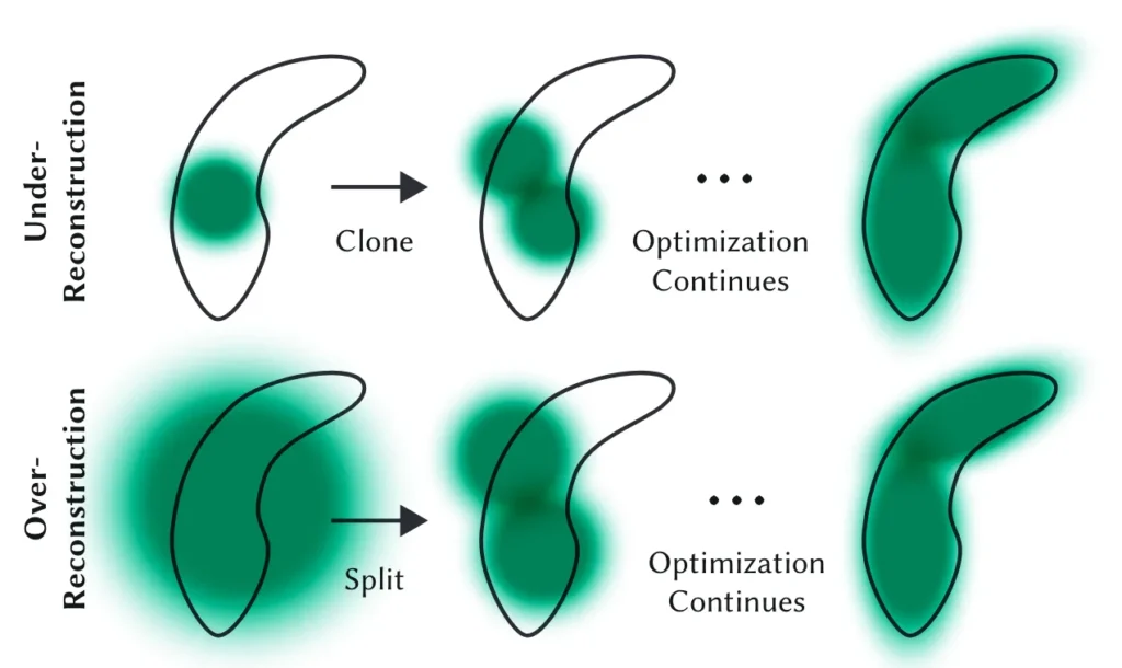
Example showing adaptive density control of a gaussian to best represent a detail resembling a bean shape. Top row (under-reconstruction): When small-scale geometry (black outline) is insufficiently covered, we clone the respective Gaussian. Bottom row (over-reconstruction): If small-scale geometry is represented by one large splat, we split it in two. Source: Taken from here.
To summarize - The Gaussian Splat training basically tries to use a differentiable Rasterization technique and an optimization method to train each gaussian to best match & represent the real world 3D scene and it stretches, scales, moves, splits or clones gaussians as needed to represent the details in the scene. At the end of these steps, what you get is a really good quality 3D Gaussian Representation of your scene.
If you would like to try running these steps and create a GSplat for yourself from your video or photos, Nerfstudio is a good tool that provides a command line API that allows for a simplified end-to-end process of creating, training, visualizing and testing Gaussian Splats.

The Vision ✨📺
Ok, so now how do we render these 3D Gaussian Splats and view amazing Real world scenes in 3D?We use a fast tile-based Differentiable Gaussian rasterization method.We’ve been throwing around this term for a while now. Don’t worry, we’ll look into what this is!

In short, differentiable Gaussian rasterization renders Gaussian Splats by:
Projecting each Gaussian from the camera perspective
Sorting Gaussians by depth (i.e. proximity to the image plane/screen)
Rendering each gaussian, with backward and forward propagation of the gaussians to blend their transparencies(alpha values) as smooth gradients on the screen.
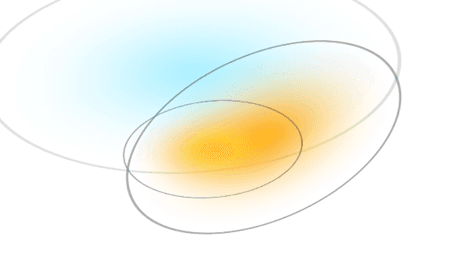
Multiple splats rendered together. Here you can see the transparent splats blending together.
In detail, a fast differentiable tile-based rasterizer is used to render Gaussian Splats. Let’s take a look at the steps involved.
First, the screen is split into 16x16 pixel tiles.
For each tile - 3D Gaussians are grouped into the tile’s view frustum it belongs to, based on its position in 3D space. Some gaussians overlapping with multiple tiles can be assigned to all the tiles it overlaps.
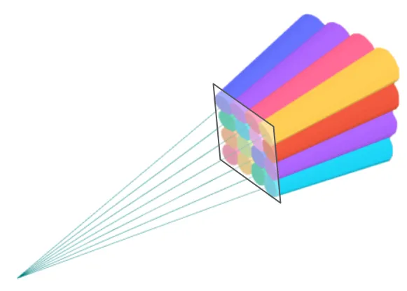
View frustums, each corresponding to a 16x16 image tile. The colors have no special meaning. The result of the sorting algorithm is a subset of 3D points within each tile sorted by depth. [Source: Taken from here]
Before rendering, all 3D Gaussians within a tile are sorted/ordered by depth (i.e. proximity to the image plane/screen). This allows for alpha(α) blending of the relevant 2D gaussians only. Thanks to sorting, the rendering workload of each pixel can now be reduced to alpha blending of pre-ordered gaussians from the tile the pixel belongs to. The alternative would be sorting the gaussians while rendering each pixel to know which gaussian should be rendered first along with the blending of other gaussians, which you can understand would be very compute expensive.
Now, for all the pixels within a tile, each Gaussian is rendered, with first a forward pass (reading front-to-back) & then a backward pass (reading back-to-front) of the sorted gaussians within that tile, and their transparencies (alpha values) are blended to render the gaussians as smooth gradients on the screen, giving a great quality rendering of the scene.
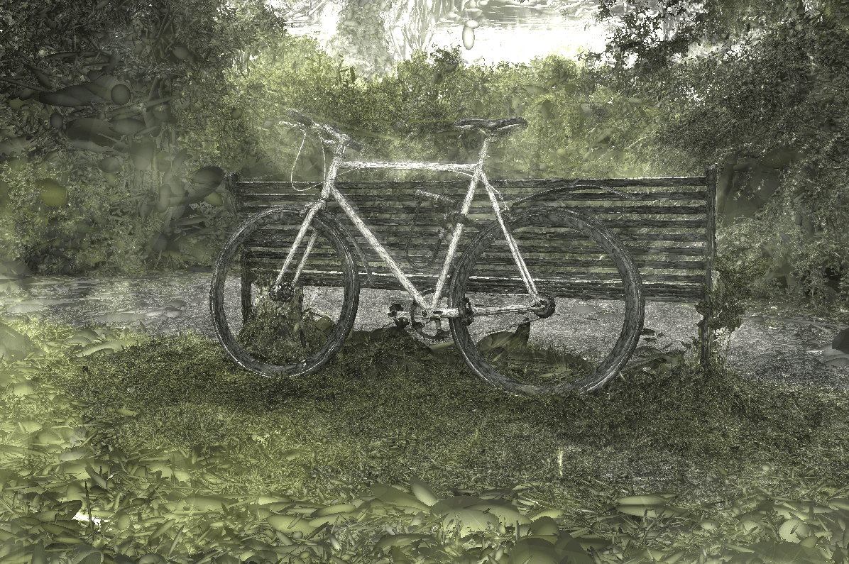
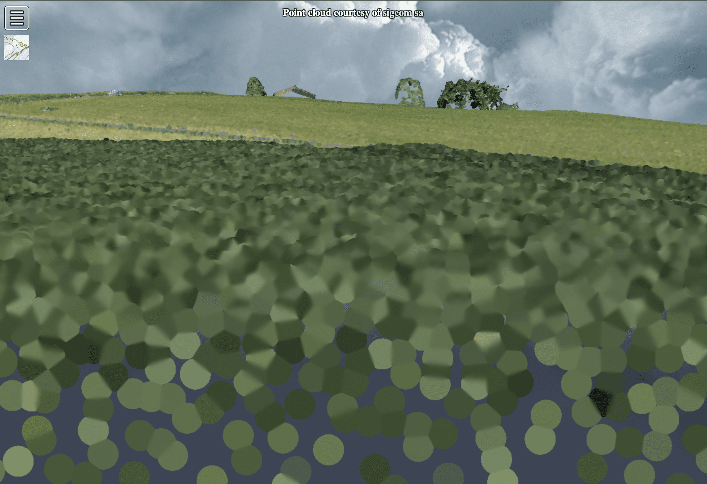
Scene represented as 3D Gaussians.
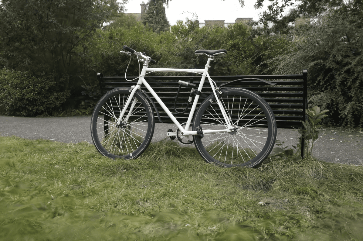
3D Gaussians rendered as 2D Gaussians with alpha blending. Look at the fine grass details.
This tile based sorting & rasterization approach reduces the compute & rendering workload, making fast real-time rendering times possible!
View Dependent Effects
In rendering of GSplats, View dependent rendering is used, but not for LODs or to unload objects out of view to avoid using too much memory and overloading the hardware, though it maybe good to explore in future for large-scale GSplat scenes. Here it is rather used to render anisotropic (or view dependent) effects of Gaussians. Color & covariance (shape) of a Gaussian is anisotropic, meaning it depends on the view direction (camera viewpoint). As mentioned earlier, this is how it is able to reproduce reflections on a surface from the source images. To store and render these view dependent effects, Spherical harmonics are used.
Spherical harmonics (SH) are functions used to represent patterns on a sphere. SH coefficients are stored with each gaussian, which is then used in rendering anisotropic effects according to the view direction. We won’t be going into much detail about SHs here, as this is outside the scope of this post (exhausted in corporate).
Finally.. take a look at this amazing 3D Gaussian Splatting scene below. Now that you’ve taken a peek at the behind the scenes of GSplats, I hope you have a newfound appreciation for this technology!
Luma Example
Play around with this scene, zooming into the finer details, seeing the gaussians and notice how each splat changes on view direction. Most of all, feel how photorealistic this is! ✨
Summarizing all that we discussed above - 3D Gaussian Splatting is a new way of 3D scene representation & reconstruction using anisotropic 3D Gaussians with a fast rasterization method to train at high speeds to create a near-realistic & compact representation of the scene, and also provide good real-time rendering of these scenes.
Alright, to load these GSplats into a viewer, and to render it, we’ll need loaders that work with our Renderer of choice. Fortunately, there have been good loader libraries developed by the open source community such as GaussianSplats3D (a Three.js renderer combined with GSplat loader) and by companies such as Luma AI - luma-web (WebGL, Three.js & React Three Fiber libraries). For our Viewer, we have used luma-web as our Loader with our Renderer being the same as before, built using Three.js & React Three Fiber.
The Future of 3D Gaussian Splatting!
The potential of 3D Gaussian Splatting seems really exciting. There is a lot of work being done, and support being added for Game engines such as Unity, Unreal Engine, VFX softwares such as Houdini and 3D design tools such as Spline. This means that the future of Gaussian Splatting being used for storytelling and many other forms of interactive media seems quite promising.
There are also people developing animatable human gaussians to scan and create photorealistic digital humans from photos or existing video, relightable gaussians to add our own lighting effects to Gsplats and advancements on top of GSplat such as Trilinear point splatting. Me personally, I have been working on a video game based on a real world location in Rishikesh, India. I’m excited to try creating my environments, by capturing drone footage, converting it into GSplats and importing into a game engine like Unreal Engine to try it out!
I hope you will also be a part of experimenting with this technology rather than just going with the hype train. I am sure there will be a lot more exciting advancements & applications coming up in this space!
NeRF vs Gaussian Splatting
Before we end this post, let’s take a look at the predecessor to 3D Gaussian Splatting - Neural Radiance Fields (NeRFs) to understand what got us to this place. NeRF is another novel view synthesis method that uses neural networks.
Novel view synthesis, as a field has existed for quite some time, but the development of machine learning technologies has accelerated the growth of this field. Neural networks for 3D scene reconstruction, representation and rendering has been an area of exploration by many computer graphics researchers & engineers.
NeRF uses neural networks to sample a continuous volumetric light field, otherwise known as radiance field. A radiance field is a volumetric representation of light in a scene, similar to how our eyes see the world through light reflected from objects. NeRF then uses a light-weight MLP (a type of neural network) on the frontend to render the scene. This is very cost expensive and getting real-time rendering speeds via this method is hard.
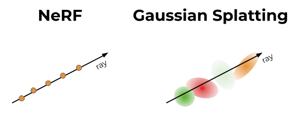
While NeRF deals with creating a function for space, Gaussian Splatting involves generating gaussian point clouds to represent space.
3D Gaussian Splatting is also a method that is used to represent a radiance field but it uses Gaussians as a base for representation without using any neural networks, along with a fast rasterization method which makes both training & rendering faster.
NeRFs are much harder and slower to render compared to 3DGS, as for each camera viewpoint, a query needs to be done to the neural network representation of volumetric field (scene) to understand what color to shade each pixel with. On the other hand, the advantage with Gaussian splatting is that a neural network isn’t needed to render the scene, as the values needed are already stored in the gaussians which can be easily rendered as splats with the tile-based rasterization approach. This makes real-time rendering much faster(up to 120FPS in some cases), and great quality scenes could be rendered with lesser computing power.
Also, GSplats can train really fast (without the use of neural networks) for great quality 3D reconstruction. The 3D Gaussian representation, with the fast tiled rasterizer helps in training great quality scenes at faster speeds compared to a NeRF with similar quality (which may take up to 48 hours).
That being said, NeRFs are still a great technology and it may not be out of the game just yet. Being a rapidly evolving field that 3D reconstruction is, who knows, with newer hardware and technical developments, new forms of NeRF could catch up to be faster and better formats.
Concluding Notes
I hope this post was able to give you a good understanding of what goes into the making of a Render Engine, the First Principles approach & as an extension, what 3D Gaussian Splatting is and why it’s changing the game. I believe you can take this knowledge and apply it for building your own 3D apps. Rather than a method, this is more a way of thinking. Keep that in mind & good luck with your projects!
Also, If you wanna reach out to me with any questions, work inquiries or interesting collaborations, say you wanna build something with Gaussian splats, work on a 3D Render Engine, or you have something else that I could help you build - I’d be happy to talk!
Connect with me through my socials: Michael Jernil at LinkedIn | GitHub | X or schedule a call at 3D ENGINERD. 3D ENGINERD is the One-person company through which I help startups and companies looking to build exciting 3D applications - with R&D, Engineering, Development, Consulting & what not. Ah.. a subtle plug! ✨
I will also continue to write posts here at my Blog - What The Graphics! with this 3D Gaussian Splatting post being the first one, thanks to Radiance Fields. This post will be up on my Blog as well, starting next week. If you’re looking to delve deep into Computer Graphics and are looking for simple resources on Complex Graphics concepts, WTG! is focused to help you out with that! 🧊 Blog requests are welcome as well.
If any of the subject experts here notice any mistakes in the content of this post, please let me know and I’d be open to take a look and do the necessary revision, as I’m also a student in these technologies. We’ll keep updating this post & the accompanying Viewer repo, as new developments come up. Feel free to bookmark & come back here anytime!
3D Gaussian Splatting - Resources 🛠️
The below are a bunch of 3D Gaussian Splatting Resources that we’ve organized for you. If you want to learn more about GSplats and try out any libraries, viewers, editors and plugins, feel free to use this ever updating list!
Suites
Viewers
Editors
Plugins
Unity
Blender
Unreal Engine
Houdini
Papers
Creative Stuff

New to Gaussian Splatting? Start here